Adventures debugging a SH1106 OLED Display (Voltages disappear!)
Why do I even have it?
I recently pulled out electronics I had purchased over 3 years ago, from my storage box. It was a Raspberry Pi Pico that I infrequently used, a 16-key capacitive touchpad, and a 1.3 Inch OLED Display module. On their own these parts are nothing special, their original purpose was to be turned into a phyiscal handheld console for retro games, specifically run CHIP-8 games on these three devices using an emulator I had written. The emualtor after being written, never saw the light of day. I was bad at electronics and had very little to no knowledge. I have improved over-time.
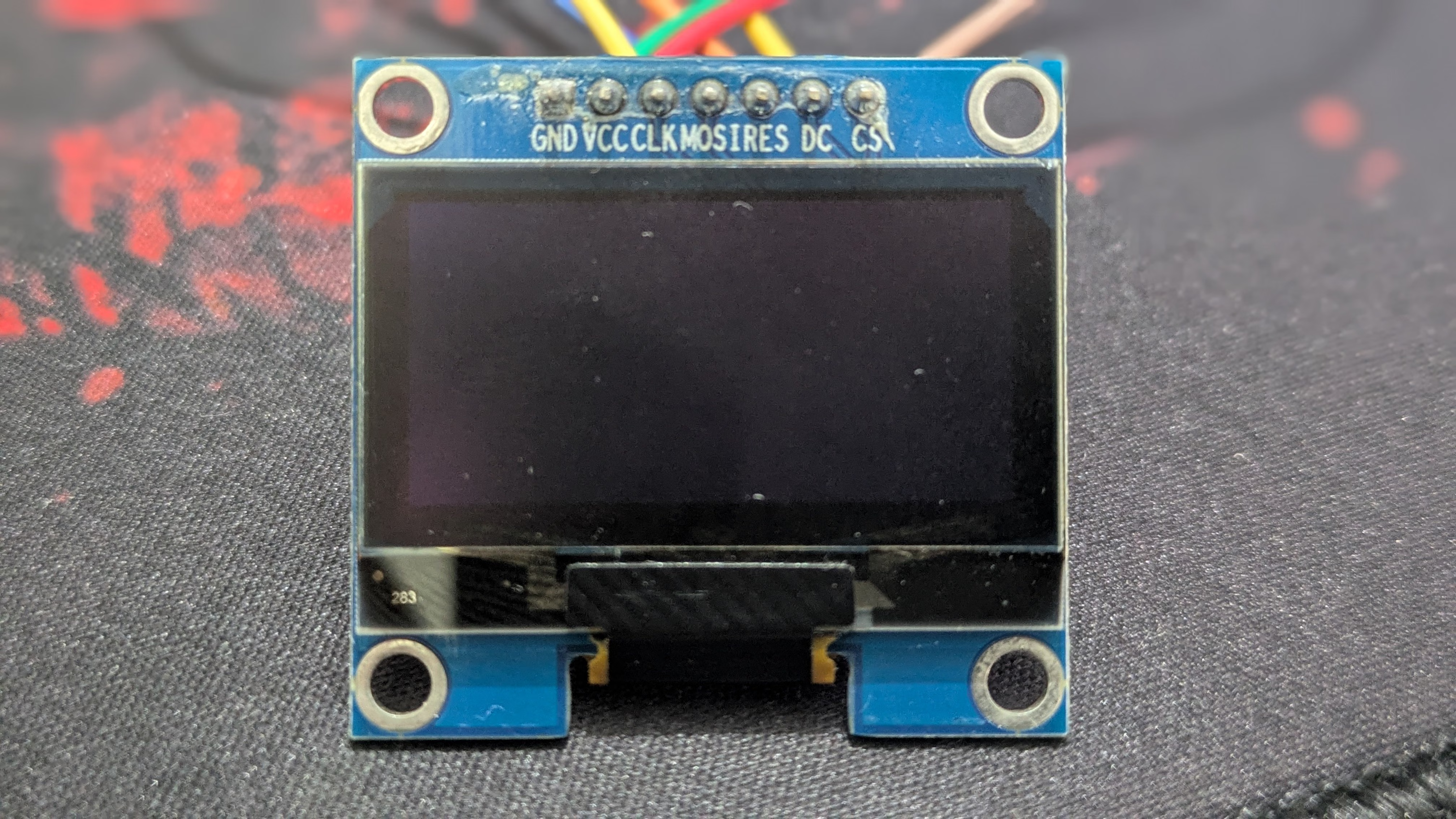
It supports both I2C and SPI modes for driving it. By default, it came with SPI soldered with a tiny resistor, and a setup suitable for SPI mode. I wired up the the connections according to the pin labels on the module onto a breadboard my pico rested on. Flashed micropython on the pico so it made testing and debugging my hardware easier, and got to work. The driver code for the SH1106 module was rather easy to find. One simply uploads it to the device and your own code itself, and it shall simply work. OR, it shan’t. The display refused to turn on, with no sign of what was wrong. It was a blank off-state screen and the display reacted to nothing.
Debugging
The Code
import utime
import machine
import sh1106

spi = machine.SPI(0, baudrate=1000000, sck=machine.Pin(18),
                  mosi=machine.Pin(19))
dc = machine.Pin(17)
res = machine.Pin(20)
cs = machine.Pin(16)

oled = sh1106.SH1106_SPI(128, 64, spi, dc, res, cs)
oled.sleep(False)

while True:
    oled.fill(1)
    oled.show()
    utime.sleep_ms(50)
    oled.fill(0)
    oled.show()
    utime.sleep_ms(50)
I first checked the code with other common sh1106 examples I found on the internet in-case I did something wrong, however, everything appeared to be normal. It is quite tiny and it’s hard to make critical mistakes with a pre-written and tested driver. So next was the module itself, which I already suspected to be faulty. This is because when I had purchased the devices, I tested them and the display did not work back then as well. I just chalked it up to my skill issue with programming and not knowing enough about reading datasheets and electronics.
The Module
I first wired the module as shown here:
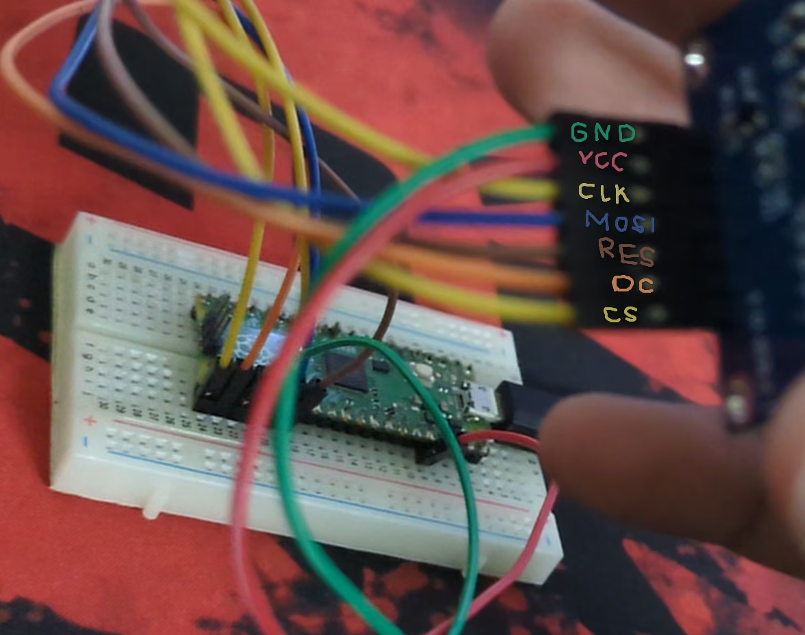
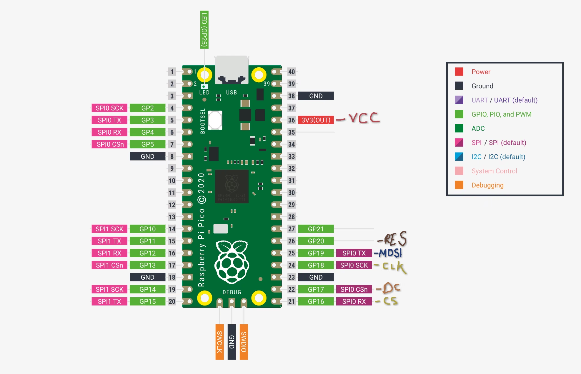
If you notice here, I accidentally put CS on SPI0 Rx and DC on SPI0 CSn, while it matters for code using default layouts, I am manually specifying the GPIO pins here so it should not be an issue. Regardless, it was in a workable state. Now it was time to measure out the voltages between the ground pin (GND) and each of the rest. According to the datasheet1, and when buying – it was clearly stated that it operates on 3.3V which is what my pico should output. Using my multimeter, the results were odd, especially for VCC, MOSI, and CLK pins.
- (GND,VCC) = 2.6V
- (GND,CLK) = 0.04V
- (GND,MOSI) = 0.04V
- (GND,RES+DC+CS) = ~3.1V
Code running on the pico, trying to use the module
There is a voltage fall-off! Which means something on the module is shorted and causing a voltage drop on the pico’s voltage output. These measurements were taken while my code was running on the pico. So I decided to reset the power-state, i.e nothing was running on the pico and took the measurements again, which resulted in the following:
- (GND,VCC) = 3.26V
- (GND,CLK) = 3.13V
- (GND,MOSI) = 2.89V
- (GND,RES+DC+CS) = ~0V
No code, module simply connected to the pico
This just tells me whenever the Pico tries to operate, there is a voltage fall off caused on the internal data bus somehow.
I’m not very familiar with all the electronics on this module so I just googled on how to proceed with debugging, which just uses gemini in its overview results. It simply suggested I try and measure the capacitors behind the module using a multimeter in continuity mode, perhaps the ribbon cable’s connections are damaged, the pico’s spi bus was stalling, breadboard issues, wiring the RESET line directly to 3.3V output2.
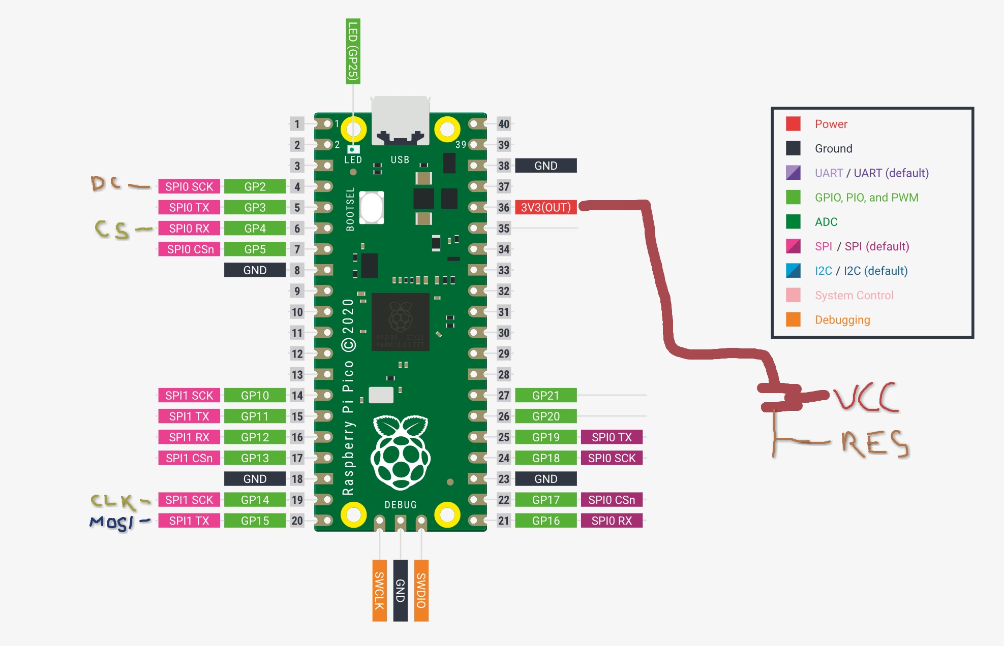
I tried all of these with new jumper connections to the pico with the following code and layout and it changed nothing.
New Layout with code and connections
- Code
import utime
import machine
import sh1106

# Tried connecting everything far away so as to note
# any changes in voltage or behavior
spi = machine.SPI(1, baudrate=1000000, sck=machine.Pin(14),
                  mosi=machine.Pin(15))
dc = machine.Pin(2)
res = machine.Pin(3) # Dummy
cs = machine.Pin(4)

oled = sh1106.SH1106_SPI(128, 64, spi, dc, res, cs)
oled.sleep(False)

while True:
    oled.fill(1)
    oled.show()
    utime.sleep_ms(50)
    oled.fill(0)
    oled.show()
    utime.sleep_ms(50)
- Pin Connections
- (GND,VCC) = 3.26V
- (GND,CLK) = 3.13V
- (GND,MOSI) = 2.89V
- (GND,RES) = 3.27V
- (GND,CS+DC) = 0.01V
No code, module simply connected to the pico
The running code results are same as above with normal, non-hardwired RES connection.
Results
The code-runtime and normal observations remained the same, a voltage drop when the code was running. Shorting checks for the capactiors and other parts behind the module, and the ribbon cable did not show any faults.
My assumption on what may be happening:
- During the no-use state, it behaves normal, an SPI device ready to be used. There is no voltage fall off and doesn’t indicate any issues.
- When attempting to use, the CS, DC and RES lines get pulled high, which indicates to the module it is ready to be used.
- When the master controller (pico) tries the CLK and MOSI lines, there is an internal short circuit–somewhere on the display matrix, it causes the voltage drop and we have our dead OLED Display module
OR IS IT? While I was writing above assumption on results, I decided to take one final measurement just to make sure my data was correct. Using normal connections as before, I measured the pins.
- (GND,VCC) = 3.26V
- (GND,CLK) = 3.09V
- (GND,MOSI) = 2.93V
- (GND,RES+DC+CS) = ~0V
No code, module simply connected to the pico
Okay, that’s normal, now let me try with the code trying to use the display
- (GND,VCC) = 3.26V
- (GND,CLK) = 0.06V
- (GND,MOSI) = 0.05V
- (GND,RES) = 3.26V
- (GND,CS+DC) = ~3.1V+
No code, module simply connected to the pico
Even more surprising results!
WHAT? where did the voltage drop go? Huh? I had measured the device several times before writing and made sure to take notes of the readings. They’ve all turned on me, it’s like there is no voltage drop at all. I repeated this again, disconnected jumpers and connected again. Took readings without the RPi using it, and while using it. Same result. There isn’t a voltage drop. So what’s going on?
I have no idea what happened in the span of me deciding to write, reaching the Results section, and deciding to re-verify my results for one final time.
With these results, I decided to measure the charge capacitors behind the display to make sure they were boosting the voltage properly. According to page 3 of the datasheet1 C1 and C2 are pump capacitors, their job is to boost to Vpp (6.4V - 14.0V) (page 35)1. Lo and behold, I use my multimeter and they are sitting flat at 3.24V with the power passing straight through them instead of getting boosted to operating voltage.
This is the true root cause as of current observations. The module simply isn’t able to reach operating voltages. However, I do not know what I have done wrong before, I even repeated the swapping of CS-DC pins mistake I had before but it did not result in any difference (it shouldn’t). Regardless, the voltage drop will now remain a mystery to me, and atleast I have the real (supposedly) cause of death behind the module.
This was a tedious, repetitive and yet fun process. I learned how to operate a multimeter, learned to measure tiny points and think about how a device operates. A complete new adventure!
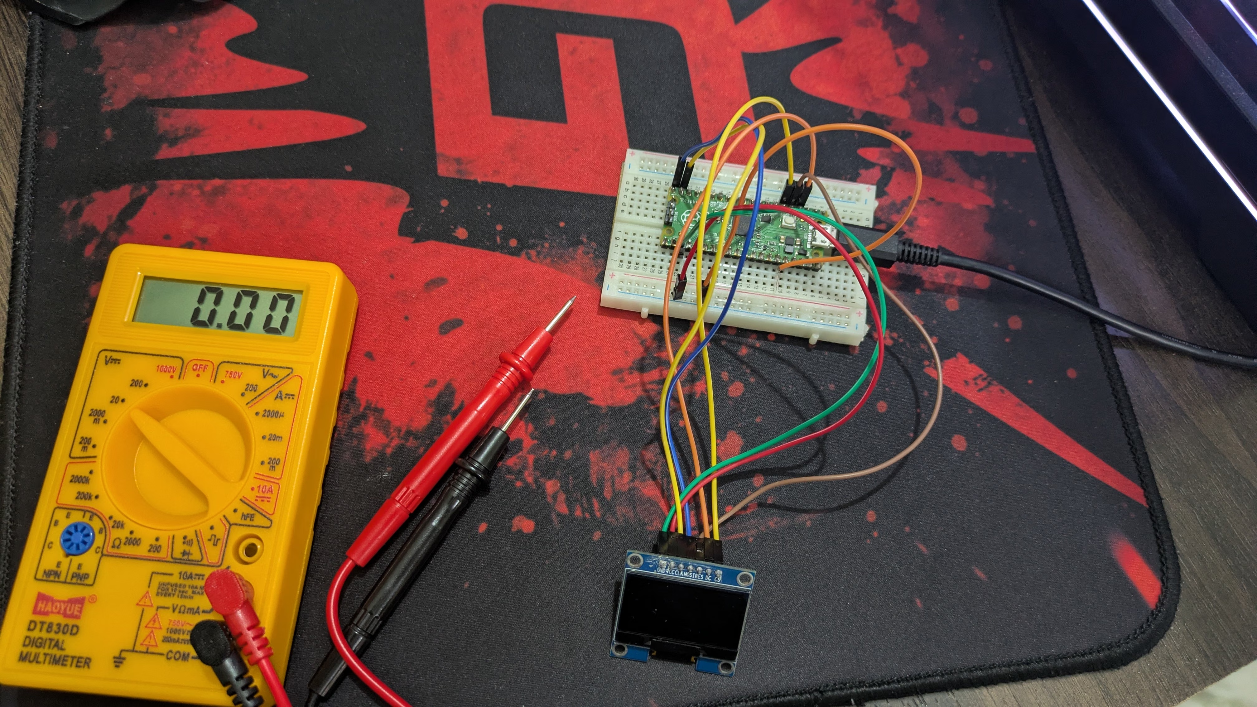
Here’s a picture of my multi-meter and my final setup hehe :3
SH1106 Datasheet – https://www.pololu.com/file/0J1813/SH1106.pdf ↩︎ ↩︎ ↩︎
The datasheet dictates that the reset line goes low during initilaization and then stays high during operation. Its reasoning for testing a hardwire to 3.3V —
Many 7-pin SH1106 SPI display modules require a massive burst of current on the physical RES (Reset) pin the exact millisecond the pin transitions from Low to High to initialize the display logic. If the display's internal reset circuit has a faulty component, driving it with a standard Pico GPIO pin will overload that specific pin's current limit, pulling the entire RP2040 chip down to 2.6V.— I’m not well learned in electronics and I only know the basics, so I’m just leaving it here. ↩︎
お茶飲みたい〜
Amrit Handa | resume | rss feed | source